Abstract: To investigate pipe-end bending during the rolling of large-diameter seamless steel pipes, this study examines pipe-end morphology and dimensional deviations and uses finite element simulations to clarify the formation mechanism and identify potential corrective measures. The results show that pipe-end bending causes deviations in pipe curvature, wall thickness, and outside diameter. It also increases material loss during end cropping and reduces product yield. An inclined end face on the mother pipe develops into a fishtail-shaped end during continuous rolling. During subsequent hollow-reduction operations in the mandrel extractor and sizing/reducing mill, the pipe end undergoes asymmetric compression, ultimately resulting in bending. Comparative simulations of pipes with and without inclined end faces confirm that end-face inclination is the primary cause of pipe-end bending. The findings indicate that optimizing the initial pipe-end geometry and improving the uniformity of the rolling force distribution can effectively reduce pipe-end bending.
Modern large-diameter continuous pipe rolling mills offer high production capacity, high dimensional accuracy, and a high degree of automation. These capabilities enable them to meet market demand for:
- Large-diameter seamless steel pipes
- Pipes with high diameter-to-wall-thickness ratios
- Pipes made from high-alloy steels
The main production stages include billet heating, piercing, continuous rolling, mandrel extraction, and sizing or reducing. Through multi-stand rolling, the mandrel extractor and sizing/reducing mill perform preliminary diameter reduction and final dimensional adjustment, respectively, to produce seamless steel pipes that meet the specified outside-diameter requirements. However, during hollow reduction, improper control of the rolling centerline, interstand tension, or pipe-end condition can cause pipe bending, resulting in deviations in outside diameter, wall thickness, and straightness. Such bending can also affect subsequent threading operations, leading to defects such as incomplete thread formation (black threads), thread eccentricity, and uneven wall thickness caused by off-center positioning or insufficient machining allowance on one side.
Based on the deformation mechanisms of longitudinal pipe rolling, previous studies have examined the effects of factors such as the friction coefficient, deformation resistance, forward slip, roll diameter, roll hardness, and workpiece temperature on pipe bending during three-roll sizing and reducing. These studies have shown that pipe bending can be effectively mitigated through several measures:
- Strictly controlling the heating temperature in the rotary hearth furnace.
- Optimizing the process parameters for piercing and continuous rolling.
- Adjusting the arrangement of sizing and reducing stands, for example, by introducing gaps between consecutive stands.
- Regulating the operating cycle of the cooling bed.
These measures help reduce the lengths of the pipe ends removed during cropping and improve overall product yield. Building on previous research, this study investigates the formation mechanism of pipe-end bending through pipe-end morphology analysis, measurements of pipe outside diameter and wall thickness, and numerical simulations. Based on the findings, corresponding measures to mitigate pipe-end bending are proposed.
Pipe bending can result from various factors, including residual stresses caused by a nonuniform microstructure and asymmetric rolling loads caused by rolling centerline deviations. This study focuses on a typical form of pipe-end bending characterized by S-shaped curvature near the pipe ends, often accompanied by inclined end faces at both the head and tail. Production experience indicates that bending severity increases with the degree of end-face inclination and the amount of diameter reduction.
As shown in Figure 1, the axial distance from the tail end face to the peak of the bend is approximately equal to the center-to-center spacing between adjacent sizing/reducing stands. Tail-end bending is generally more pronounced than head-end bending. In severe cases, multiple periodic bends develop along the pipe axis, with the distance between adjacent bends corresponding to the stand spacing, giving the pipe a characteristic bamboo-like appearance.
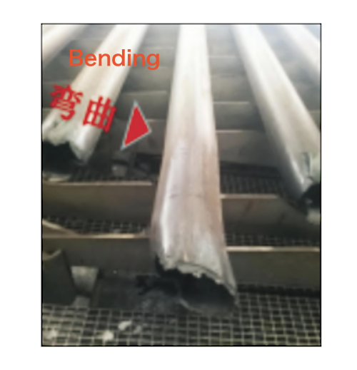
Figure 1 Schematic of pipe-end bending
API Spec 5CT–2018, Specification for Casing and Tubing, limits overall pipe curvature to 0.2% of the total pipe length and pipe-end curvature, defined as the deviation within 1.5 m of the pipe end, to 3.18 mm. Where customers specify stricter requirements, the allowable pipe-end deviation is typically reduced to 1.8 mm over the same length. Similarly, API Spec 5L–2018, Specification for Line Pipe, limits overall curvature to 0.2% of the total pipe length and pipe-end deviation to 3.2 mm within 1.5 m of the pipe end.
The most direct quality issue caused by pipe-end bending is excessive curvature beyond the specified limits. For casing, which requires threading, excessive curvature can cause misalignment during centering and threading, resulting in incomplete thread formation, commonly referred to as black-mark defects. Pipe-end curvature must therefore be strictly controlled during production. Pipe sections that exceed the allowable limits must be cropped, reducing product yield. If the initial billet is too short, removing the bent section may also leave the finished pipe shorter than the required length, complicating production scheduling and process control.
A major consequence of pipe-end bending is that the wall thickness in the bent section may exceed the specified tolerance. To investigate this effect, a Φ377 mm × 14 mm pipe for liquid service was selected as a representative example. Wall thickness was measured at different distances from the tail end to the region near the bend. According to GB/T 8163–2018, Seamless Steel Pipes for Liquid Service, the allowable wall thickness for this pipe is 11.9–16.1 mm (±15% of the nominal wall thickness). However, the maximum measured wall thickness at 760–860 mm from the pipe end was 16.9 mm, exceeding the upper limit. At 760 mm from the pipe end, the wall-thickness deviation reached 21% of the nominal value, well above the specified ±15% tolerance. Therefore, at least 860 mm of the pipe end must be cropped to ensure compliance, and the required cropping length may increase further when wall-thickness nonuniformity is considered. Measurements from other pipe specifications show a similar pattern: maximum wall thickening and minimum wall thickness typically occur 750–850 mm from the pipe end, coinciding with the region where pipe-end bending occurs, generally 800–850 mm from the end. This spatial correspondence suggests a close relationship between pipe-end bending and excessive wall-thickness deviation.
Under the same rolling rhythm and furnace-discharge temperature, two typical fluid-service pipe specifications, Φ377 mm × 14 mm and Φ426 mm × 15 mm, were compared. The Φ377 mm × 14 mm pipe, which underwent a greater diameter reduction and passed through more sizing/reducing stands, exhibited more pronounced wall-thickness variations near the pipe-end bend. In contrast, the Φ426 mm × 15 mm pipe, with a smaller diameter reduction and fewer sizing/reducing stands, showed a more gradual variation in wall thickness in the same region.
Pipe-end bending can cause the outside diameter (OD) to exceed the specified limits. However, compared with straightness and wall-thickness deviations, its effect on OD is generally less pronounced because the sizing/reducing stands help correct dimensional deviations. For pipes with an OD tolerance of ±0.75% to ±1% of the nominal OD, the relatively wide tolerance band makes OD exceedance at bends less likely. In contrast, pipes with fixed dimensional tolerances, such as ±1.6 mm or an asymmetric tolerance of −0.8 to +2.4 mm, have a narrower tolerance band and are more susceptible to OD exceedance at bends. For example, ASTM A333/A333M–2013, Standard Specification for Seamless and Welded Steel Pipe for Low-Temperature Service, specifies an allowable OD range of 323.0–326.2 mm for a Φ323.8 mm × 9.53 mm pipe. An OD measurement of 326.3 mm at a bent section therefore exceeds the specified upper limit.
To investigate the development of pipe-end bending and identify its underlying mechanism, tail-end deformation was observed at four key stages along the production line.
Hollow shell after piercing: The tail end remains relatively straight, with no significant bending, although the end face is slightly inclined.
Rough pipe exiting the continuous rolling mill: During continuous rolling, the rolls and mandrel reduce the pipe diameter and wall thickness while elongating the shell. The high rigidity of the straight mandrel prevents significant tail-end bending. However, the tail develops a pronounced oblique end face and a fishtail-shaped section that protrudes beyond the pipe body. At the inlet of the mandrel extractor, a guide tube with a conical bore directs the pipe into the machine. As the deformed tail passes through the guide tube, it strikes the inner wall, producing a loud, sharp impact.
Pipe shell after mandrel extraction: After leaving the continuous rolling mill, the shell is removed from the mandrel by the detacher and transferred by a turnover arm to a small cooling bed. Observations reveal noticeable curvature at the shell ends, with the fishtail section appearing flattened or deformed, as shown in Figure 2.
Finished pipe after sizing/reducing: Tail-end curvature becomes more pronounced after the pipe passes through the sizing/reducing mill. Comparative observations show that a greater number of sizing/reducing stands, corresponding to a higher degree of diameter reduction, is associated with a longer oblique end section and more pronounced bending. These observations suggest that deformation during mandrel extraction and sizing/reducing causes the pipe tail to bend upward, further increasing its curvature.
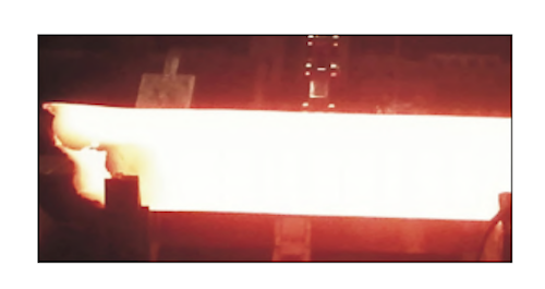
Figure 2 Schematic of upward tilting and bending of mother pipes on the small cooling bed
The observations described above indicate that an oblique end face, also known as a horseshoe end, is already present at the tail of the hollow shell after piercing. During continuous rolling, the inclined end face becomes more pronounced, and a fishtail-shaped tail develops, although this phenomenon is not observed in medium- to thick-walled pipes. As the pipe passes through the detacher and sizing/reducing mill, tail-end curvature increases. In general, the greater the number of sizing/reducing stands the pipe passes through, the more severe the bending becomes.
Preliminary analysis suggests that pipe-end bending originates from either temperature differences across the billet cross-section or nonuniform metal flow during piercing. Both mechanisms can produce oblique end faces on the hollow shell. The subsequent formation of pipe-end curvature involves the following stages:
Formation of an oblique end face: Uneven temperature distribution or nonuniform metal flow during piercing produces an inclined end face at the tail of the hollow shell.
Development of the fishtail: During continuous rolling, the oblique end face elongates and may develop into a fishtail-shaped tail. This deformation is generally absent in medium- to thick-walled pipes.
Further deformation during downstream processing: As the pipe passes through the guide tube at the detacher inlet, the detacher, and the sizing/reducing mill, contact and compressive forces cause further tail-end deformation. In medium- to thick-walled pipes, where a fishtail does not develop, interaction with the guide tube can still contribute to bending. The cumulative deformation ultimately produces the observed pipe-end curvature.
Numerical simulation has been widely used to study piercing, continuous rolling, and sizing/reducing in seamless steel pipe production. The simulation results generally agree well with physical observations in terms of deformation patterns and trends, making it possible to reproduce manufacturing processes virtually and predict rolling behavior with reasonable accuracy. With advances in computing technology, numerical simulation has become an increasingly valuable tool for analyzing metal deformation during seamless pipe rolling and optimizing continuous rolling processes.
Although on-site observations provide some insight into the formation of pipe-end bending, safety requirements, equipment obstructions, and the high speed of the moving pipe make it difficult to observe the deformation process in detail. Finite element analysis is therefore used to investigate the underlying mechanism. The simulation model is developed using actual production parameters, including temperature, rolling speed schedules, roll-pass geometry, and pipe dimensions. The simulation results are then analyzed to clarify the metal deformation mechanisms under specific process conditions.
Based on production experience, pipe-end bending appears to be closely associated with the oblique end face at the pipe tail. To investigate this relationship, a typical 20 steel pipe measuring Φ377 mm × 14 mm was selected as the study case. An initial set of simulation models was developed to simulate the hollow shell as it passed sequentially through the guide tube, detacher, and sizing/reducing mill, allowing the development of pipe-end bending to be examined throughout these operations.
(1) Passage Through the Guide Tube
The inlet guide tube of the detacher directs the hollow shell into the machine and prevents the pipe head from striking the machine frame, which could interfere with the initial bite. Accordingly, the guide tube has an inner diameter only slightly larger than the outside diameter of the pipe entering the first stand of the detacher. However, the fishtail that develops at the tail of a thin-walled hollow shell during continuous rolling may protrude significantly beyond the pipe body, making contact with the guide tube's inner wall likely as the shell passes through. When the fishtail is sufficiently large, it strikes the inner wall of the guide tube. As the deformed tail is progressively flattened against the wall, the resulting lateral force deflects the pipe tail in the opposite direction, causing the pipe to bend as it enters the first stand of the detacher. To quantify this deformation, a two-dimensional cross-section was extracted from the three-dimensional simulation model, and the pipe-end curvature was measured. The resulting bending deflection was 7.7821 mm, as shown in Figure 3. This result indicates that lateral displacement of the pipe body under the force exerted by the guide tube contributes to the observed pipe-end bending.
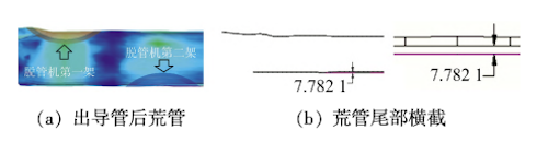
(a) Mother pipe after passing through the guide tube (b) Cross-section of the mother pipe tail
Figure 3 Schematic of shell-tail bending caused by fishtail flattening against the guide tube
(2) Passage Through the Detacher
As the fishtail at the tail of the shell exits the continuous rolling mill and passes through the detacher's guide tube, it is compressed and its height decreases. Further flattening occurs when the shell enters the detacher because the pass opening is smaller than the inner diameter of the guide tube. A two-dimensional model was extracted from the three-dimensional simulation model of the shell after detachment to measure the tail-end curvature. The measured deflection on the inner side of the bend was 6.2757 mm, as shown in Figure 4.
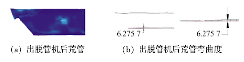
(a) Mother pipe after exiting the detacher (b) Measured mother pipe curvature after detachment
Figure 4 Schematic of tail-end bending after the mother pipe passing through the detacher
(3) Passage Through the Sizing/Reducing Mill
A two-dimensional model was extracted from the three-dimensional simulation model of the shell after it passed through the sizing/reducing mill. The measured deflection on the inner side of the tail-end bend was 3.66 mm, as shown in Figure 5.
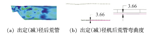
(a) Hollow shell after passing through the sizing/reducing mill (b) Measured tail-end curvature at the mill outlet
Figure 5 Schematic of tail-end curvature measurement after the sizing/reducing mill
The simulations of hollow-shell deformation in the guide tube, detacher, and sizing/reducing mill demonstrate that numerical simulation can effectively reproduce the shell's bending behavior. The results also indicate that the oblique end face of the shell plays a key role in the formation of pipe-end curvature.
To investigate how pipe-end bending develops within the mill stands, simulation results for hollow shells with and without an oblique end face were compared. During production, the shell undergoes hollow reduction as it passes through the guide tube, detacher, and sizing/reducing mill. The distance between the guide tube and the first stand of the detacher is comparable to the interstand spacing within both the detacher and the sizing/reducing mill. In addition, the detacher and sizing/reducing mill have identical nominal stand diameters, roll-groove profiles, and interstand spacings. The simulation model was therefore simplified to focus on shell deformation in the sizing/reducing mill. A typical 20 steel shell measuring Φ377 mm × 14 mm was selected, and a second set of simulations was performed to analyze its deformation as it progressively entered the fourth stand.
(1) Deformation of a Hollow Shell with an Oblique End Face
As a hollow shell with an oblique end face enters the fourth stand, the long and short sides of the inclined end contact the roll surface at different times. The longer side makes contact first. Once this side is gripped by the fourth stand, the roll surface progressively presses it downward, forcing the pipe end to deflect laterally in the opposite direction. This deformation gradually produces a bend with its vertex near the groove bottom of the third stand and a bending angle of θ, as illustrated in Figure 6. When the pipe end reaches the fourth stand while the bending point remains near the third stand, the bending span is approximately equal to the interstand distance.
As the shell passes through successive stands, diameter reduction causes further bending deformation at the pipe end. Consequently, a greater number of stands and a higher overall reduction ratio tend to increase the length of the oblique end section and the severity of bending. After the shell passes through the sizing/reducing mill, a two-dimensional model is extracted from the three-dimensional simulation model to measure the end deflection. The measured value is 1.7921 mm, as shown in Figure 7.
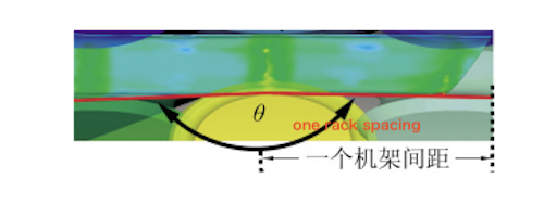
Figure 6 Schematic of pipe-end bending in a mother pipe with an oblique end face
(a) Shell after exiting the sizing/reducing mill (b) Measured pipe-end bending at the mill outlet
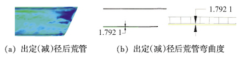
(a) Mother Pipe After Sizing (or Reducing) (b) Bending of the Mother Pipe After Sizing (or Reducing)
Figure 7 Measurement of pipe-end bending in a mother pipe with an oblique end face
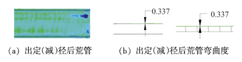
(2) Deformation of a Hollow Shell with a Square End Face
When a hollow shell with a square end face enters the fourth stand, its leading end contacts the upper and lower roll surfaces simultaneously. The shell advances essentially horizontally, without significant lateral displacement or rotation, and therefore undergoes little bending. A two-dimensional model extracted from the three-dimensional simulation gives a pipe-end deflection of 0.337 mm, as shown in Figure 8.
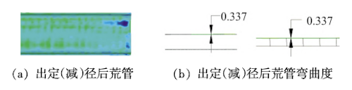
(a) Shell after exiting the sizing/reducing mill (b) Measured pipe-end bending at the mill outlet
Figure 8 Numerical measurement of pipe-end bending in a mother pipe with a square end face
The comparison between pipes with oblique and square end faces indicates that end-face inclination is a major contributor to pipe-end bending.
(3) Comparison of Simulation Results
Figure 9 compares the simulated pipe-end deflections under different conditions. In the multistage deformation process involving the guide tube, detacher, and sizing/reducing mill, shells with oblique or fishtail-shaped ends are susceptible to pronounced bending as they pass through these components. By contrast, a shell with a square end face undergoes only minor bending when subjected to sizing/reducing alone. The simulated deflection is well below the 1.8 mm limit specified for casing. However, although the simulated deflection of a shell with an oblique end face remains below the 1.8 mm limit after a single sizing/reducing pass, actual production involves additional process variations and operating conditions. The resulting pipe-end curvature may therefore exceed the allowable limit.
(a) Mother pipe after sizing (b) Bending of the mother pipe after sizing
Figure 9 Comparison of simulated pipe-end bending values
Technical note: The original text states that the long side of the oblique end is pressed downward, causing the pipe end to deflect in the opposite direction. Please verify that the direction of this displacement matches the simulation results in Figure 6. Also, the 1.8 mm casing limit should be cited to the applicable standard or customer specification in the final paper.
The preceding analysis indicates that pipe-end bending can develop at multiple stages of production, including when the hollow shell interacts with the mandrel bar and as it passes through the detacher and sizing/reducing mill. The primary cause is the oblique end face of the hollow shell, which results in nonuniform force distribution during subsequent rolling and leads to bending. An effective approach is therefore to reduce the force imbalance acting on the deformed pipe end.
One potential solution, suggested in previous studies, is to introduce a tail-end trimming or swaging operation before hot sizing/reducing. Removing the obliquely cut portion of the pipe tail would produce a more nearly square end face, reduce asymmetric loading during subsequent rolling, and help limit pipe-end bending. This approach may also reduce the length of material removed during final end cropping, thereby improving material yield.
- Pipe-end bending is a common defect in large-diameter continuous rolling of both thin-walled and medium- to thick-walled pipes. It can cause the outside diameter, wall thickness, and curvature near the pipe ends to exceed the specified tolerances, increasing the amount of material removed during end cropping and reducing product yield.
- By combining on-site observations with numerical simulations, this study investigated the development of pipe-end bending as the hollow shell passed through the mandrel, detacher, and sizing/reducing mill, and quantified the resulting deformation. Comparison of the simulation results with measurements from physical pipe samples demonstrated that numerical simulation can effectively reproduce the pipe-end bending process.
- Simulations of a mother pipe progressively entering the fourth stand of the sizing/reducing mill revealed the mechanism of pipe-end bending. When a mother pipe with an oblique end face enters a stand, its longer and shorter sides contact the rolls at different times. As the longer side is gripped and pressed downward by the rolls, the pipe end is forced to deflect laterally in the opposite direction. This produces a bend whose vertex is located near the groove bottom of the preceding stand, with a bending span approximately equal to the interstand distance.