Abstract: This study investigates the failure causes of a low-alloy steel tower base round tube that fractured in a specific project. The analysis of the fatigue fracture of the base tube was conducted using macroscopic morphology examination, SEM (scanning electron microscopy), EDS (energy dispersive spectroscopy) for micro-area chemical composition analysis, inclusion analysis, metallographic structure analysis, and tensile performance testing. The findings indicate that, during use, the steel tube experienced overheating under load, leading to partial uneven deformation. The crack initiation occurred at an inner boss crack in the tube’s middle section. Under reciprocating alternating loads, the crack propagated, ultimately resulting in the fatigue fracture of the tower crane base tube.
Low-alloy hot-rolled steel strips are highly regarded for their strength, toughness, ease of processing, and good weldability. These qualities make them ideal for use in industries such as construction, bridges, and shipbuilding. Among these, hot-rolled low-alloy round tubes are commonly used to produce tower crane base tubes due to their solid mechanical properties and cost-effectiveness. However, during the vertical motion of the tower crane base tube and its supporting frame, friction-induced overheating can occur, leading to fatigue pitting. Additionally, exposure to harsh environmental conditions such as wind, rain, extreme temperatures, and freezing cold can lead to surface corrosion and fatigue fractures, posing significant safety risks. This study focuses on a low-alloy steel tower base tube that failed due to fatigue during a construction project. To understand the failure, we used various analysis tools, including metallographic microscopy, scanning electron microscopy (SEM), and energy-dispersive X-ray spectroscopy (EDS). These methods helped us examine the microstructure, defect morphology, composition, and precipitates. The analysis identifies the causes of the fatigue fracture and the factors that may have contributed, offering valuable insights for improving production processes and ensuring better construction safety.
The steel pipe used in the test was a tower base pipe made of low-alloy steel strip, which had experienced fatigue fracture during the construction process of a certain project. The steel pipe had been in service for two years and was discovered to be fractured by on-site construction personnel during routine equipment maintenance. The failed steel pipe was then cut and sampled using a CNC DK7780 wire-cutting machine. After the sample was ground, polished, cleaned, and air-dried, its chemical composition was analyzed using a German SPECTROLAB direct-reading spectrometer. A metallographic sample was prepared by cutting, polishing, and etching with a 4% nitric acid alcohol solution, and metallographic observations were conducted using an OLYMPUS BX53M optical microscope. The average size of the original austenite grains was determined using the intercept method with Image Pro software. The fatigue fracture morphology of the failed steel pipe was examined using an OLYMPUS BX53M scanning electron microscope, and the chemical composition of the micro-precipitates and impurities in the failed tube was analyzed using the EDS probe in the scanning electron microscope.
The surface of the round tube shows clear signs of rust, with no noticeable macro plastic deformation at the fracture site. The yellow anti-rust paint on one side has been completely worn off, and there is noticeable cyclic load wear in the middle of the tube. However, no significant wear is observed at either end. The crack appears in the middle of the round tube, with a weld nodule on one side, and the other side exhibits distinct cracks. These cracks are long and deep, running along the length of the tube (longitudinal cracks in the rolling direction of the steel strip). The center of the crack side is dark purple (or black), indicating overheating under load and partial uneven deformation. As the steel strip is not heat-resistant, the reciprocating friction during use leads to significant blackening of the friction contact surface in the middle. Although there is no overburning at both ends, there are relatively continuous pits, which exhibit a fatigue pitting morphology.
Sampling was conducted by wire cutting perpendicular to the crack direction. The cross-section of the longitudinal crack fracture is relatively flat, with no obvious burrs but partial rusting. The crack has penetrated the full thickness of the steel strip. A boss is visible in the middle of the fracture, with an obvious transverse crack within the boss gap, approximately 2/3 of the thickness. The thickness of the steel pipe is 4.5mm. Under reciprocating overload stress, the boss is likely to concentrate stress, leading to the formation of microcracks, which, under alternating bending loads, become the source of fatigue cracks. There is a circle of shear lips on the outermost layer of the inner ring of the round tube, indicating that the inner surface is the last to fail. This suggests that the fracture process of the tower base round tube expands from the outer surface to the inner surface. The shear lip area constitutes about 10% of the total fracture area, indicating that the stress causing the final fracture is not particularly large. Therefore, the fracture mode of the failed round tube is identified as a high-cycle fatigue fracture caused by reciprocating stress.
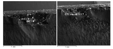
As shown in Figure 1 and Table 1, spectra 1, 2, and 3 display light-colored abnormal structures, primarily containing Fe, O, C, Ca, S, Mn, Si, Al, K, Cl, and other elements. This is primarily due to oxidation at the fracture and boundary areas, with point oxides appearing around these regions. These oxides segregate at the grain boundaries, leading to intergranular fracture in the iron alloy. Simultaneously, the content of highly corrosive elements such as S and Cl is extremely low, suggesting that corrosion is not the cause of the fracture failure. It is more likely to be a result of fatigue fracture. The extremely low levels of Si, Ca, and Al may originate from the deoxidation products during the steelmaking and refining stages, and they have little influence on the fracture. Spectrum 4 displays the dark-colored matrix, which primarily contains Fe, O, C, Mn, Si, Ca, Ti, and other elements, with the matrix structure appearing normal.

Figure 1: SEM Morphology of the Fracture
Table 1: Chemical Composition of EDS Spectrum Points at Cracks
|
Element |
Spectrum 1 (%) |
Spectrum 2 (%) |
Spectrum 3 (%) |
Spectrum 4 (%) |
|
C |
21.26 |
20.04 |
27.71 |
7.77 |
|
O |
29.46 |
33.03 |
31.81 |
2.56 |
|
Mg |
|
0.18 |
|
|
|
Al |
0.10 |
0.07 |
0.15 |
0.13 |
|
Si |
0.40 |
0.35 |
0.18 |
0.19 |
|
S |
0.81 |
0.62 |
0.7 |
|
|
Cl |
0.09 |
0.34 |
0.07 |
|
|
K |
0.22 |
0.20 |
|
|
|
Ca |
1.96 |
1.93 |
0.41 |
0.58 |
|
Ti |
|
|
|
0.04 |
|
Cr |
|
|
|
|
|
Mn |
1.20 |
0.95 |
1.11 |
0.27 |
|
Fe |
44.50 |
42.29 |
37.81 |
88.46 |
|
Mo |
|
|
|
|
|
Ba |
|
|
0.05 |
|
|
Total |
100 |
100 |
100 |
100 |
Non-metallic inclusions disrupt the continuity of the steel matrix. Additionally, the inclusions themselves or the voids created by them can act as small gaps. When the parent material is subjected to alternating loads, stress and strain concentrations are easily formed, which can become the source of fatigue fractures in steel pipes. Metallurgical studies demonstrate that soft inclusions (e.g., Class A MnS) exhibit 20-30% higher thermal expansion coefficients than the base steel matrix due to their enhanced deformability under thermal cycling, potentially leading to interfacial stress concentration.
The compressive stress generated in the matrix has little effect and does not significantly impact the fatigue performance of the steel pipe. However, inclusions like oxides and silicates, which have a smaller expansion coefficient than the matrix, create tensile stress in the matrix, thereby having a greater impact on the fatigue performance. This is also one of the reasons for fatigue fractures in pipes.
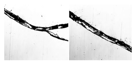
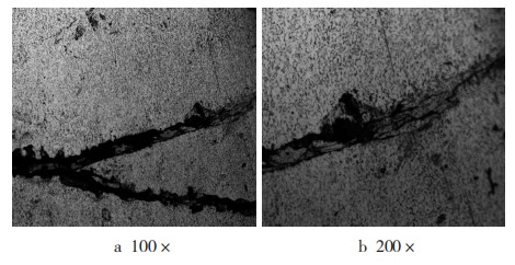
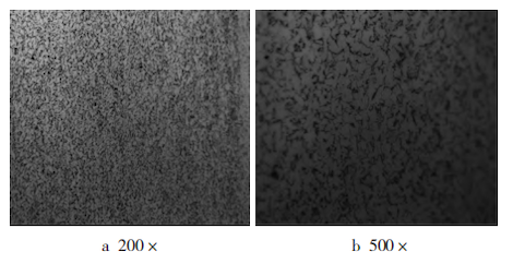
Therefore, the parent material was inspected for inclusions under a microscope. As shown in Figure 2, the purity of the matrix at and near the crack is very high, and no significant inclusions were observed. As seen in Figure 3, the grains at the crack are approximately 10 microns in size, with no apparent decarburization or precipitation of Si and Mn oxides at both ends of the crack, ruling out the possibility of an original crack in the ingot. The grains at the crack are fine, showing a transgranular cracking morphology. Stress deformation is present in the grains inside the crack and in the surrounding grains. The crack morphology indicates stress cracking and fatigue fracture. As shown in Figure 4, the matrix metallographic structure is fine, with a ferrite + pearlite structure, and no significant abnormalities were found.

Figure 2 Inclusions at the crack 100x

Figure 3 Metallographic structure at the crack

Figure 4 Metallographic structure of the steel pipe matrix
The factory inspection warranty for the steel strip material of the steel pipe is reviewed, and tensile specimens are taken from the cracked pipe using wire cutting. Normal pipes and unused pipes, which have been welded with the same brand, specification, and bending process as the cracked pipe, are selected. The mechanical properties are tested in accordance with GB/T 228-2010 "Room Temperature Tensile Test Method for Metallic Materials." The results are presented in Table 2.
Table 2 Tensile performance test results
|
Sample description |
Yield strength (MPa) |
Tensile strength (MPa) |
Elongation after fracture (%) |
|
Factory steel strip warranty inspection results |
445 |
529 |
27.0 |
|
Unused round tube tensile specimen after welding |
542 |
597 |
23.0 |
|
Used uncracked round tube tensile specimen after welding |
541 |
606 |
22.5 |
|
Used round tube tensile specimen 1 |
552 |
626 |
22.0 |
|
Used cracked round tube tensile specimen 2 |
560 |
630 |
21.5 |
It can be seen from Table 2 that the composition and performance of the factory steel strip meet the standard requirements. The tensile performance after pipe fabrication is influenced by factors such as work hardening and the welding cooling method. The yield strength and tensile strength increase by approximately 80 MPa and 60 MPa, respectively, while the elongation after fracture decreases by 4%. This is because the base material undergoes plastic deformation during the pipe forming process at room temperature. The grains in the matrix elongate and rotate along the direction of maximum deformation, leading to dislocation entanglement, lattice distortion, and the combined effects of intracrystalline and intercrystalline fracture. This results in grain elongation, breakage, and fiberization, which further enhances resistance to slip deformation. Residual stress accumulates within the base material, causing an increase in strength and hardness, while plasticity and toughness decrease by 10%.
When comparing the tensile properties of unused, normally used, and cracked round pipes after pipe bending and welding, the cracked round pipe exhibits higher strength and lower elongation, but the increase is limited. The pipe bending and welding process has a certain impact on fatigue fracture, but this influence is also limited.
(1) The fracture of the low-alloy steel strip tower base round tube is caused by fatigue. The crack originates from a transverse crack at the gap of the boss in the middle of the round tube. The steel matrix is relatively pure, without inclusions or large-particle precipitates that significantly affect performance. The grains are fine and uniform, and the metallographic structure is normal.
(2) The steel pipe is exposed to outdoor service year-round, with significant temperature fluctuations between day and night, as well as between seasons. Rain, smoke, and high-altitude operations introduce considerable changes to the service environment, leading to a reduction in the fatigue strength of the parent material. Furthermore, high-frequency reciprocating operations cause the anti-rust paint on the side of the steel pipe to wear off. The surface defects resulting from the rust layer can easily form stress concentration crack sources, which induce the matrix to fracture and fail.
(3) The tensile properties of the tower base round tube after bending and welding are influenced by factors such as work hardening and the welding cooling method. The strength and hardness of the parent material increase, while its plasticity and toughness decrease, resulting in significant changes to the mechanical properties. Optimizing the bending and welding processes, minimizing surface defects such as scratches during processing, and reducing stress concentration crack sources can effectively extend the service life of the tower base round tube.