Abstract: This study investigates the metallographic structure, microhardness, and influence of a laser-cladded 625 alloy layer on the mechanical properties and sulfide stress corrosion resistance of carbon steel pipe. The cladding layer consists primarily of columnar crystals with a small amount of dendritic structures. After applying a 0.5 mm-thick nickel-based 625 alloy layer to the inner wall, the yield strength of N80Q-grade steel pipe increased by 47 MPa, while the transverse impact energy decreased by 10 J. The hardness at the center of the cladding layer is 304 HV0.5, with values of 340 HV0.5 and 327 HV0.5 on either side of the fusion line, and 351 HV0.5 near the surface. Laser cladding with a nickel-based 625 alloy significantly enhances the resistance of medium-carbon chromium-molybdenum steel casing to hydrogen sulfide stress corrosion.
Bimetallic composite pipes retain the advantages of both the base metal and the cladding alloy, while their cost is only 1/5 to 1/2 that of pipes made entirely from corrosion-resistant alloys. Compared with pure alloy pipes, bimetallic composite pipes offer improved safety and reliability in chloride-containing and acidic environments. Unlike mechanically bonded composite pipes, metallurgically bonded pipes feature a strong bond at the interface between the two metals. Common methods for producing such pipes include hot extrusion, hot rolling, centrifugal casting, explosive welding, and powder metallurgy.
Laser cladding is an advanced surface modification technology in which cladding material is applied to the substrate surface and melted together with a thin surface layer of the base material using a high-energy-density laser beam, forming a metallurgically bonded coating. This technology is widely used in the surface modification of gas turbine blades, rollers, gears, rotors, molds, and in the repair of downhole tools in the oil industry. Common cladding materials include nickel-based, cobalt-based, iron-based, titanium and copper alloys, as well as ceramic materials. Compared with other surface treatment methods, such as arc welding, thermal spraying, electroplating, and vapor deposition, laser cladding offers numerous advantages: rapid heating and cooling, minimal thermal distortion, low dilution, strong metallurgical bonding, uniform and dense microstructure, excellent wear resistance, easy automation, short processing cycles, high material utilization, and the ability to create functionally graded materials. It is widely regarded as a high-quality, energy-efficient, material-saving, and environmentally friendly process.
The demanding operating conditions in oil and gas fields have raised performance requirements for oil well pipes, particularly with respect to mechanical strength and corrosion resistance. Corrosive environments containing CH₄, H₂S, and CO₂ often lead to pipe degradation. Sulfide stress corrosion cracking, hydrogen-induced cracking, pitting, and general corrosion are common causes of pipe failure. Studies have shown that laser cladding nickel-based alloys onto the inner walls of CI10-grade oil pipes effectively improves resistance to hydrogen sulfide stress corrosion. Cladding a nickel-based 625 alloy onto the inner surface of carbon steel casing enhances its corrosion resistance when exposed to corrosive fluids or gases. This technology is also applied to threaded connections to ensure continuous protection along the entire wellbore. In this study, a nickel-based 625 alloy was laser-cladded onto the inner surface of carbon steel pipe. The cladding quality was analyzed and evaluated in terms of metallographic structure, hardness, bonding strength with the substrate, mechanical performance, and resistance to sulfide stress corrosion.
This study investigated the metallographic structure, composition, and hardness of the cladding layer, its bonding strength with the substrate, and its influence on mechanical properties. The substrate material was a medium-carbon manganese seamless steel pipe with an N80Q steel grade and specifications of 339.72 × 12.19 mm. A 0.5 mm-thick nickel-based alloy 625 layer was clad onto the inner wall. To evaluate its effect on the stress corrosion resistance of high-grade sour service casing—particularly under hydrogen sulfide (H₂S) environments—a 125 ksi-grade medium-carbon Cr-Mo seamless steel pipe (244.48 × 11.99 mm) was selected.
In accordance with NACE TM0177-2016, Standard Test Method for Laboratory Testing of Metals for Resistance to Sulfide Stress Cracking and Stress Corrosion Cracking in H₂S Environments, the cladding material was first machined. The gauge section, transition arc, and other areas of the specimen that would be exposed to the corrosive solution were machined to be 1 mm smaller in diameter than the standard dimensions. Nickel-based alloy 625 was then clad onto the surface of the prepared substrate. To ensure surface smoothness and uniform cladding thickness, manual polishing was carried out after the cladding process. The final gauge diameter of the specimen met the standard requirement of 6.35 ± 0.13 mm, with a surface roughness of no more than 0.25 μm.
The steel pipe manufacturing process followed the sequence: tube blank → piercing → hot rolling → heat treatment → straightening → nondestructive testing → inspection and storage.
The chemical composition of the cladding layer was analyzed using a Bruker XFlash 5030 spectrometer. Samples were taken from the inner wall of the N80Q pipe after cladding with alloy 625. The specimens were coarsely ground, finely ground, polished, and then electrolytically etched in a 10% oxalic acid aqueous solution for 5–8 seconds. The microstructure was subsequently observed using a ZEISS AIM universal metallographic microscope. The hardness of the cladding layer was measured with a Qness AT300DR-TM microhardness tester. A flattening test was carried out in accordance with SY/T 6623-2021, Specification for Corrosion-Resistant Alloy Composite Steel Pipes with Internal Coating or Lining. Sulfide stress corrosion testing was performed using stress ring specimens provided by Cortest, USA.
The base steel pipe is medium-carbon manganese steel, while the cladding layer is made of nickel-based alloy 625. To better observe the carbon steel substrate, its heat-affected zone, and the structure of the cladding layer, the substrate and heat-affected zone were etched using a 49% HNO₃ and alcohol solution, while the cladding layer was electrolytically etched using a 10% oxalic acid aqueous solution. Figure 1 shows the microstructure of the carbon steel substrate near the inner wall cladding layer at (a) 100× magnification and (b) 200× magnification. The region of the substrate farther from the cladding layer remains unaffected and consists of tempered troostite. In contrast, the substrate near the cladding layer is affected by the transient thermal input of the laser heat source. Depending on the distance from the heat source, the carbon steel substrate can be divided into a quenched zone and a tempered zone. Figure 2 shows the transverse microstructure of the cladding layer. After electrolytic etching, the fusion line appears as a bright white structure. This is attributed to convective mass transfer between the molten pool during laser cladding and the interface with the carbon steel substrate.
Convective mass transfer in the molten pool promotes thorough mixing between the nickel-based alloy and the molten substrate. This leads to non-uniform nucleation within the pool, where grains grow in the direction opposite to heat flow, forming a bright white columnar crystal structure oriented perpendicular to the inner wall. The cladding layer is primarily composed of a γ-Ni solid solution, which contains a substantial amount of eutectic structure along with a small quantity of dark-phase compounds. The eutectic structure consists of the γ-Ni solid solution and various carbides.
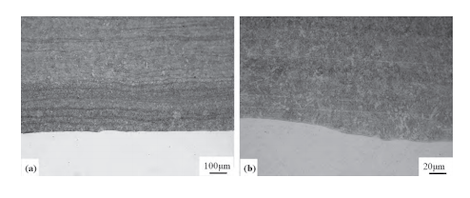
(a) 100X; (b) 200X
Figure 1 Microstructure of carbon steel matrix near the inner wall cladding layer
According to solidification theory, the morphology of the solidified structure is governed by the ratio of the temperature gradient to the solidification rate (G/R), also referred to as the crystallization parameter. Most fusion lines in the cladding layer exhibit a columnar crystal structure because the metal substrate, with its high thermal conductivity, facilitates rapid heat dissipation during the initial stage of cladding. This behavior aligns with the thermodynamic principles of metal solidification. As a result, the columnar crystals grow perpendicular to the substrate. As the inner wall cladding process progresses, heat gradually accumulates in the carbon steel substrate and its surrounding environment. This accumulation reduces the rate of heat dissipation from the cladding layer, thereby promoting the formation of a dendritic microstructure.
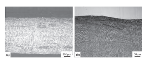
Figure 2 Microstructure of the cladding layer at (a) 100× and (b) 200× magnification
Figure 2 shows the microstructure of the cladding layer at (a) 100× and (b) 200× magnification. Further microstructural analysis was conducted using scanning electron microscopy (SEM), as shown in Photo 3. In the SEM image, the dark regions correspond to the 625 nickel-based alloy matrix, while the bright regions indicate the presence of intermetallic compounds and carbides. The compositions of both the matrix and the intermetallic/carbide phases were analyzed using energy-dispersive spectroscopy (EDS) attached to the SEM, and the results are summarized in Table 1.
Table 1. EDS Energy Spectrum Analysis (wt%)
|
Locations |
Ni |
Cr |
Fe |
Si |
C |
Nb |
Nb |
|
Columnar Product |
59.90 |
21.79 |
8.59 |
4.19 |
0.21 |
5.33 |
0 |
|
Compound |
43.77 |
20.17 |
9.93 |
3.16 |
0.64 |
12.34 |
9.64 |
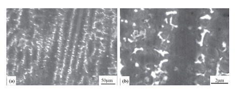
(a) 3000×; (b) 10000×
Figure 3. SEM observation of the cladding layer microstructure
Microhardness testing (HV0.5) was carried out on the carbon steel substrate, on both sides of the fusion line, at the center of the cladding layer, and near the surface of the cladding layer. The results are shown in Figure 4. The test data indicate that the microhardness of the carbon steel substrate is 259 HV0.5. The hardness values on the two sides of the fusion line are 340 HV0.5 and 327 HV0.5, respectively. At the center of the cladding layer, the microhardness is 304 HV0.5, while the surface region of the cladding layer exhibits the highest hardness, measuring 351 HV0.5. The 625 nickel-based alloy powder contains elements such as Ni, Cr, Fe, Mo, and Nb. When rapidly heated by a high-energy laser beam, these elements diffuse and quickly solidify at the interface near the substrate and within the fusion zone. This process leads to an increase in hardness near the fusion line.
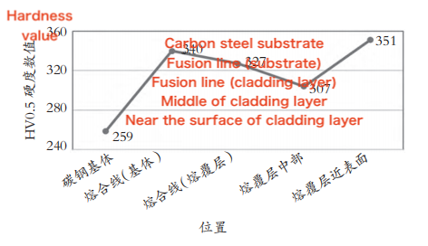
Figure 4. Comparison of microhardness between the base metal and the cladding layer
Tensile and transverse full-size impact tests (impact notch KV8, test temperature 0°C) were conducted on N80Q steel grade medium carbon manganese steel specimens measuring 339.72 × 12.19 mm, as well as on samples with approximately 0.5 mm of nickel-based 625 alloy cladding on the inner wall. The yield strength of the base steel pipe was 669 MPa, with a tensile strength of 792 MPa and an elongation of 31.5%. After cladding, the inner wall exhibited a yield strength of 716 MPa, tensile strength of 808 MPa, and elongation of 30.5%. The average transverse full-size impact energy of the base material was 140 J, while the average impact energy for the transverse test on the inner wall clad with the nickel-based 625 alloy (with the cladding layer fully intact) was 130 J. The mechanical property test results indicate that laser cladding significantly influences the yield strength and transverse impact performance of the steel pipe. Specifically, the yield strength increased by 47 MPa, while the transverse impact energy decreased by 10 J.
To evaluate the bonding strength between the cladding layer and the steel pipe substrate, a flattening test was conducted in accordance with the SY/T 6623-2021 standard, “Specification for Corrosion-Resistant Alloy Composite Steel Pipes with Internal Covering or Lining.” A pipe section measuring 150 mm in length (with a minimum required length of 63.5 mm) was placed between two parallel plates, and a cold flattening test was conducted in two stages. The first stage was a ductility test. Before the distance between the two plates was reduced to less than H, no cracks, fractures, or coating peeling were permitted on the inner surface, outer surface, or edges of the specimen. The value of H was calculated using formula (1):

Where:
H = distance between the flattening plates (mm)
t = specified thickness (mm)
D = specified or calculated outer diameter based on the inner diameter and wall thickness (mm)
The second stage was the integrity test. Flattening continued until the sample either fractured or the two tube walls came into contact. Throughout this process, no peeling was allowed between the cladding layer and the base steel tube. Figure 5 shows the morphology of the steel tube sample after flattening, with the inner wall clad with the 625 alloy.
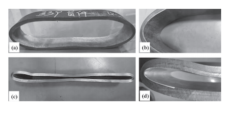
(a) and (b) Ductility test; (c) and (d) Integrity test
Figure 5. Morphology of the flattened steel tube sample with inner wall cladding
A medium carbon chromium-molybdenum alloy steel pipe, grade 125 ksi with dimensions of 244.48 × 11.99 mm, was selected for the study. The A-method stress corrosion test was conducted in accordance with the NACE TM0177-2016 standard, titled "Standard Test Method for Laboratory Testing of Metals for Resistance to Sulfide Stress Cracking and Stress Corrosion Cracking in H₂S Environments." The test conditions included the NACE TM0177-2016 standard A solution, pure hydrogen sulfide, room temperature, and a loading stress of 758 MPa × 85% (theoretically calculated to be below the specimen’s yield strength). The test duration was 720 hours. All three specimens clad with the 625 alloy passed the A-method test without failure after 720 hours.
The actual yield strength of the base steel pipe material was 911 MPa, tensile strength was 1,031 MPa, elongation was 26%, and hardness was HRC 35.0. To compare the effect of the cladding layer on sulfide stress corrosion resistance, the base material was also subjected to the A-method stress corrosion test under similar conditions: NACE TM0177-2016 standard A solution, pure hydrogen sulfide, room temperature, loading stress of 758 MPa × 80%, and a test duration of 720 hours. All three base material samples failed the test, with fracture times of 18, 15, and 20 hours, respectively (see Figure 6). The results demonstrate that laser cladding with nickel-based 625 alloy significantly enhances the resistance of medium carbon chromium-molybdenum casing steel to hydrogen sulfide stress corrosion, enabling it to pass the A-method test under severe H₂S corrosion conditions.

(a) Base material (b) Cladding with 625 alloy
Figure 6. A-method test results of base material and clad samples
- The cladding layer consists mainly of columnar crystals, with a small amount of dendrites.
- Applying approximately 0.5 mm of nickel-based 625 alloy cladding to the inner wall increases the yield strength of the N80 grade carbon steel pipe by 47 MPa, while reducing its transverse impact toughness by 10 J.
- Microhardness testing shows that the hardness at the center of the cladding layer is 304 HV0.5, while the hardness on both sides of the fusion line is 340 HV0.5 and 327 HV0.5, respectively. The surface hardness near the cladding layer reaches 351 HV0.5. The flattening test confirms a strong bond between the cladding layer and the carbon steel substrate, with no peeling or delamination observed during testing.
- Laser cladding with nickel-based 625 alloy significantly enhances the hydrogen sulfide stress corrosion resistance of medium carbon chromium-molybdenum steel casing.