2.1 Metallographic analysis
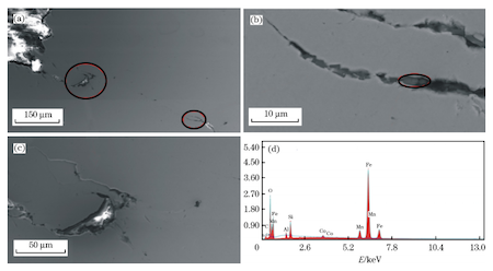
Using JEM-2800F focused ion beam-electron beam double-beam electron microscope and energy spectrometer made by FEI Instruments Co., Ltd., USA to observe and analyze the cross-section and longitudinal section, it was found that the depth of the crack can reach 0.6mm, and there are chain-like inclusions near the crack. The cracks vary in length and width, and some cracks can reach 1mm; a composition analysis of the inclusions was conducted and it was found that the elements are mainly O, Fe, Al, Si, Ca, and Mn.
The main components of inclusions are SiO2, Al2O3, MnO and other C-type inclusions. It is also found that the crack propagates along the direction of the inclusions. Energy spectrum analysis of a large number of long strip-shaped inclusions in the longitudinal section specimen found that such inclusions are also type C inclusions. Type C silicate inclusions are plastic inclusions that will be rolled into long strips in the rolling process, destroying the lateral continuity of the steel and reducing the processing performance of the steel. The formation of stress fractures in metal can be divided into three stages: crack initiation, crack propagation, and fracture. When there are a large number of silicate inclusions in the welded steel pipe, microcracks will occur at the inclusions during the flattening test of the sample, and cracking will occur when the deformation reaches a certain value. On the one hand, a large number of silicate strip inclusions destroy the metal matrix and make the metal matrix discontinuous. On the other hand, the interface between the inclusions and the matrix is a stress concentration area, which is prone to cracks under load. When the load increases to a certain value, the microcracks will continue to expand and eventually cause the sample to break.
The main components of silicate inclusions are SiO2, Al2O3 and MnO; the main reason for their inclusions is the formation of high-temperature plastic inclusions when steel is deoxidized by aluminum and ferrosilicon and ferromanganese alloys are used as additives. A large number of such inclusions will seriously affect the transverse mechanical properties of the steel pipe. The presence of a large number of silicate inclusions is also the main reason for the cracking of steel pipes in the flattening test.
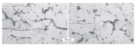
After etching with 4% nitric acid alcohol, use a Zeiss metallographic microscope to observe the tissue size and composition of the sample, and rate the sample according to the comparative method in the standard GB/T6394-2017 "Determination Methods of Average Grain Sizes of Metal". The results are shown as Level 8.0. The structural components are mainly ferrite plus pearlite, with a banded structure and no Widmanstatten structure. Based on the grain size and composition, it can be determined that the sample is not overheated or overburned. When observing the metallographic samples, it was found that there are obvious tertiary cementite structures distributed at the ferrite grain boundaries, which are interconnected and surround the ferrite grains, forming an approximate net, as shown in Figure 4. According to the iron-carbon phase diagram, it can be seen that the test steel is a hypo-eutectoid steel. During the eutectoid transformation, the ferrite in the pearlite adheres to the pro-eutectoid ferrite and grows. When cooling continues, the precipitated ferrite in the Tertiary ferrite cementite is distributed on the grain boundaries.
The literature shows that the metallographic structures that cause the flattening tested sample to fail include banded structure, Widmanstatten structure and tertiary cementite structure. The main reasons for the formation of the banded structure are composition segregation and improper hot working temperature. When the steel contains a large number of inclusions, the inclusions serve as the core for the nucleation of proeutectoid ferrite, and proeutectoid ferrite is formed around the inclusions, while austenite transforms into pearlite to form a banded structure. The banded structure caused by inclusions will destroy the continuity of the steel matrix and cause the steel pipe flattening test process to fail. The Widmanstatten structure is caused by the cooling rate being too fast or the heating temperature being too high in the rolling process. The Widmanstatten structure is characterized by a large number of parallel ferrites within the coarse austenite grains. The Widmanstatten structure has coarse grains and large amounts of flake ferrite, causing the mechanical properties of the steel to drop rapidly. No Widmanstatten structure was found in the microstructure observation of the sample, but there were banded structures and tertiary cementite structures.
Since cementite has a high hardness value, good brittleness, low strength and plasticity, and an elongation of almost 0, the plastic deformation of low carbon steel mainly occurs in ferrite. When the steel is subjected to load, deformation of matrix is hindered by cementie. When ferrite deformation is hindered by tertiary cementite, dislocations accumulate in front of the slip surface, causing stress concentration. When the stress reaches the strength limit of the matrix, cracking occurs. The generation of tertiary cementite is related to the cooling temperature. A eutectoid reaction occurs between the final rolling and the curling temperature. If the cooling rate is too slow at this time and a slow cooling occurs, the precipitation of tertiary cementite will be aggravated.

(a) Inclusions in the cross-section (b) and (c) Partially enlarged views of inclusions 1 and 2 (d) Energy spectrum of the inclusions at the positions shown in (b).
Figure 2 Microscopic morphology and energy spectrum analysis of cross-section cracks

(a) A large number of long strip-like inclusions in the longitudinal section (b) Energy spectrum analysis results of inclusions at the positions shown in (a)
Figure 3 Microscopic morphology and energy spectrum analysis of longitudinal cross-section cracks

Figure 4 Tertiary cementite in metallographic structure
(a) Fracture morphology (b) Partial enlargement morphology of the fracture (c) Fracture composition analysis at the position shown in (b)

Figure 5 Fracture morphology and composition analysis

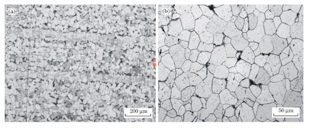
Figure 6 Metallographic structure of the improved sample at different magnifications
2.2 The analysis of the fracture
Use a tool to cut the crack to make a fracture sample. Observe and analyze the sample through a scanning electron microscope and a metallographic microscope. It is found that the crack has a wood grain layered fracture morphology, with many longitudinally distributed cracks on the surface, which is a typical layered fracture, indicating the existence of band-like structure. The longitudinally distributed cracks were magnified and observed, and it was found that there were longitudinally distributed inclusions in the fracture. Energy spectrum analysis was performed on the inclusions, and it was found that their main composition was SiO2, Al2O3 and MnO, which were similar to the long strip-shaped inclusions present in the metallographic sample, as shown in Figure 5. Analysis shows that there are a large number of longitudinally distributed elongated inclusions at the crack initiation point. The crack originates from here. The crack expands in the subsequent process and finally cracks. The fracture morphology analysis results of the defect verify the results of the metallographic test analysis.
3. Summary
Through the above analysis, it was found that the main reason for the unqualified test steel was the presence of a large number of silicate inclusions in the matrix. The secondary reason was the presence of a banded structure and a large amount of tertiary cementite at the grain boundaries, which made the plasticity of the matrix deteriorates, aggravating the occurrence of cracking in the flattening test. In view of the reasons for the failure of the above samples, the following improvement measures are proposed.
(1) Use LF refining equipment to reduce inclusions in molten steel, further improve the quality of molten steel, and improve the purity of molten steel.
(2) Optimize the steelmaking process; protect pouring; prevent secondary oxidation, and reduce the generation of Al2O3 and SiO2 inclusions.
(3) Strictly control the cooling rate in the rolling process to avoid slow cooling; regularly check whether the fan is working, and reduce the precipitation of reticular tertiary cementite.
4. Improved effect
The performance of the products processed by the LF refining furnace has been effectively improved. During the random inspection of the products, no cracking was found in the flattening test. Through metallographic analysis, it was found that the silicate inclusions in the sample were significantly reduced, and the C-type inclusions were significantly reduced, which has a grade below 1.5. The amount of precipitation of band-like structure and reticular tertiary cementite has also decreased, and the grade of reticular tertiary cementite is around 0.5. The improved metallographic structure of the sample is shown in Figure 6.